MOTORS MAINTENANCE

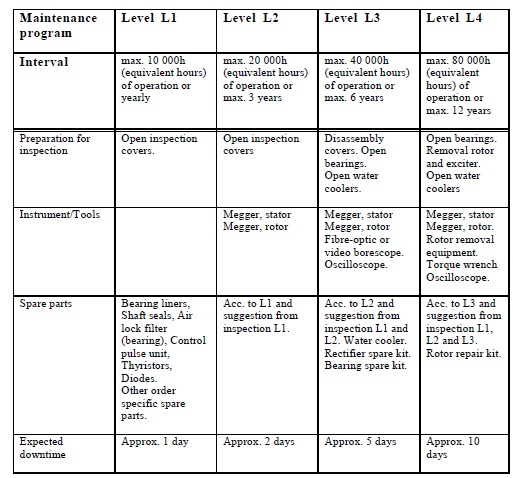
Rotating Electrical Machines needs maintanence to prevent  possible unexpected breakdowns after some calculated working hours. Such maintenance prevents unplanned stops and the  larger and expensive damages of motors and generators.

The  timing for the maintenance is depends on the type of the machine and the working conditions:

-          AC/DC,  Generator/Motor

-          Squirrel cage, Ringed

-          Bearing type

-          Protection and operation class

-          Running speed

-          The attached load;

  • Pump
  • Mill
  • Diesel Motor
  • Compressor

Ect..

Most of the time, the maintanence time is defined by the manufacturers at the users manual of the machines. Otherwise,  the experts or the operator will advice or/and decide the maintanence time and period.

It is adviced for workshop maintenance periods:

-           3 years for AC ringed engines,

-          4-5 years for squirrel cage motors and

-          2 years for DCmotors in average.

(These periods can be shortened or extended depends on the conditions of machines)

The onsite and workshop maintenance for the generators should be planned according to running hours and start numbers.

-          Equivalent hour = Total working hours + number of starts x 20 (fixed-speed engines) = 1.2 x actual working hour (variable-speed engines).

-          Option: Isolation measurement of the stator windings

-          The placement  of machine is depending on the availability/accessibility/capacity on lifting equipment

  •  IR= isolation resistance
  • PI= Polarization index

1. PRELIMINARY TEST

If possible, isolation and vibration measurements should be performed and recorded at site prior to maintenance for Motors and Generators.according these datas, before disassembly the following test should be performed;

- Isolation tests for the windings

- Measurement for RTD’s of the winding heaters, windings and housings

When possible, electrical and mechanical measurements are made and recorded for the machines by rotating them in at the nominal voltage and speed.

During the preliminary test, the following are checked and identified:

-          Status of the engine windings

-          Air space

-          Slackness of the stator, rotor and core

-          Slackness of the ring and the collector

-          Status of the bearings

-          Status of the rotor balance.

2. DRAWING OF THE COUPLINGS AND BEARINGS

a-       In case the motor has couplings or pulleys ; before disassembled, the position of shaft should be measured and recorded by caliper. The structure of the coupling needs to examine with regard to the shaft wedge. In case of locking bolt exists at the coupling, it should be  loosened.

b-       The coupling is drawn from the shaft with hydraulic drawing which has 120 degree stands without creating any tension and to prevent damages on the coupling and the shaft.

In the accompany of controlled pressure, the outer surface of the coupling is dilated by a flame heat well so that the coupling is easily drawn over the mill.

3. MEASUREMENT OF FLEXURES

-          After the coupling is disassembled, flexure measurement is performed on the shaft using a comparator. The flexure at the coupling’s middle region should not exceed 3-5%.

-          Repair of the shaft is necessary if flexure exceeds 3-5%. If load is connected to a flexed shaft, it will deviate from the axis and vibration will occur.

  • Repair with Welding:

This is not recommended as welding will stiffen the shaft and render could be fragile.

  • Coating Method:

This is not recommended due to its cost and the risk for the coupling to blister during installation and disassembly.

  • Lathe Method:

This is the recommended method. The coupling locations is corrected by lathing using the powderly pass method and afterwards, either a coupling ismanufactured according to the new measure or the interior the existing coupling is filled and processed.


  • Production of a New Shaft:

Disassembling the old shaft and manufacturing a new one is necessary if the flexure is excessive according to the shaft status.


4. MECHANIC EXPERTISE

a) The shaft bearing locations of the engine rotor is measured by the external radius

micrometer with 1% sensitivity.

b) The shaft bearing locations of the trunk cover is measured by the internal radius

micrometer with 1% sensitivity.

c) The shaft coupling location and interior sections of the coupling/pulley are also

measured by micrometers.

d) For exproof motors, all rabbet joints such as greasing flange and the connector

covers are measured by internal and external micrometers in terms of engine

properties.

The bearing tolerances are defined by the manufacturer. As a general application, the shaft is between +0 and +25 micrometers and the cover is between +0 and +45 micrometers for industrial heavy industry engines. The motor speed, housing dimension and the used bearing interval impact the tolerance amount.

5. ELECTRIC EXPERTISE

a) Isolation tests of the windings are performed.

b) HI-POT and SURGE tests are performed if necessary.

c) Megger test at 100 Volts is performed if housing isolation exists.

d) DC resistance tests are performed at 0,1% sensitivity.

e) Resistance tests are performed if there is a heater.

Resistance tests are performed if there are heat detectors.

Core tests are performed by passing the magnetic field.

Faults such as slack, ruptured bobbins and bandag

6. WASHING AND CLEANING

The windings are cleaned of all dirt by using a pressurized spray with hot water and special cleaning detergent. The application is performed in a special cabinet by/under the supervision of experienced technical staff using with appropriate protective equipment.

All motor parts as well as equipment such as covers, rotors, couplings, etc.. are washed and cleaned in the same manner.

In particular, if the generator or the engine contains special equipments, circuits, etc... mechanisms that can negatively be effected by washing, these are disassembled prior to washing.

7. KILN-DRYING AND VARNISHING

a) The motors are dried using industrial oven after washing. The kiln temperature is adjusted and

kept steady by heat control relay.

b) The oven should include fans and gas exhaust chimneys that homogeneously circulate

the air inside.

c) As a standard, the engines are kiln-dried in 100 degrees Celsius for 24 hours, and in 130 degrees Celsius for 15 hours.

d) Following the drying, the winding isolations are measured by the megger device and

they are subjected to varnishing if the measured values are matched with the standards.

e) During varnishing, the varnish applied on the hot winding which makes better contact and absorb to the windings. The heating class for varnish is very important for our application.  When varnish is not in use, it should keep in a specially equipped and vacuumed container. During application, it is sprayed  by pressurized air under a certain pressure. The motos are kilned for the same periods  as heating after the varnishing operation.

8 SANDBLASTING

The outer surfaces of the fiberglass or ceramic materials such as brush holders and connectors are covered by conductive or insulator oxide layer and dirt. Water and chemical materials are insufficient to clean the dirts. Sandblasting method provides a perfect cleaning by removing such dirts from surfaces by using  mechanical force.

9. BALANCE

The balancing according to the ISO 1940-1 standard, it requires the attention during the balancing operation of revolving parts must be on it, their installation in conformity with their post as well as the statuses of the wedge and the coupling/pulley.

The status of the wedge has been marked with the H (Half) or by the F (Full) sign on the surface of the coupling in the rotor shaft.

The balance of the coupling/pulley should also conform to this. The balance of the coupling/pulley should be full wedge if that of the rotor is Half wedge; and the coupling/pulley balance should be half wedge (without wedge) if the rotor balance is Full wedge. The rotor should be full wedge if the coupling/pulley length is shorter than the rotor wedge and the coupling/pulley should be without wedge. In cases where the rotor is half wedge and the coupling/pulley are with wedge, than the protruding section of the wedge, which is located inside of the coupling/pulley on the rotor, is cut and rendered half wedge.


10. BEARING INSTALLATION

The bearings are heated by magnetic method. Current is passed through the bearing by using devices that have automatic or manual adjusted power and the bearing is heated in a controlled manner using a heat detector. For ease of installation, the temperature to be applied on the bearing should be 80 degrees Celsius plus the ambient temperature. Higher temperatures may cause the bearing to breakdown.

Upon arriving the appropriate temperature, the device automatically decreases the voltage gradually by a demagnetization directive, there upon removes magnetism and gives a signal for its attachment. As a sudden interruption of energy may cause redundant magnetism on the bearing steel, there is breakdown risk owing to the attraction of ambient metal powders and parts

Sinus check is performed by simultaneous commencement of transmission and interruption boundaries, that emanate and rise in both alternans.

11. FINAL TEST

a)       The motors are subjected to rotation tests after the finalization of the standard isolation tests and visual examinations.

b)      It is important to provide nominal voltage for revealing breakdowns pertaining to the electrical and magnetic field.

c)        It is important to rotate with nominal revolution for the mechanical and bearing-related breakdowns. Our system can give voltage until 6000 Volts.

d)      Load test particularly attains importance in DC engines. Our system can allow a loading until 250 kW.

e)      To be sue on rotor windings and ring connections in ringed motors, one should first give nominal voltage to the stator without short-circuiting the rings, read the rotor voltage over the rotor rings and compare the label information.

f)        An FFT vibration analysis to be performed during off load condition and gE Envelop tests can provide us detailed information on vibration and the bearings.